What Is a Parking Air Heater and How Does It Work?
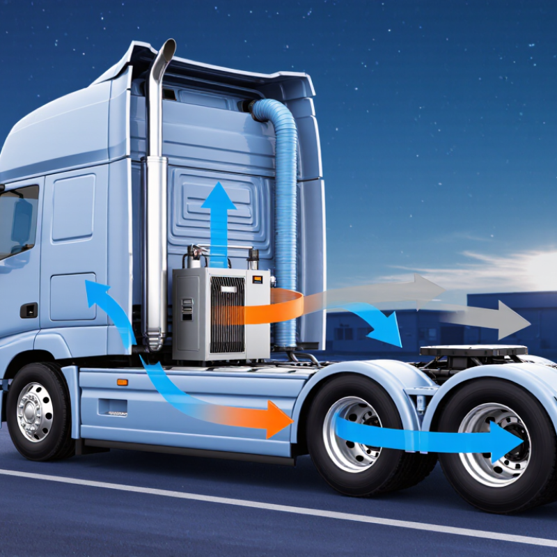
A Parking Air Heater warms a vehicle cabin without running the main engine. It usually burns a small amount of diesel or gasoline in a sealed combustion chamber. A fan pushes cabin air across a heat exchanger. Warm air then enters the sleeping or passenger area, while exhaust gases leave through a separate pipe.
The distinction matters. Engine idling produces heat, but it also consumes fuel and increases local emissions. The U.S. Department of Energy’s Idling Reduction Technology fact sheet reports that a heavy-duty diesel truck may consume about 0.8 gallons of fuel per hour while idling. A properly installed Parking Air Heater can reduce this unnecessary engine operation during overnight stops or cold loading periods. Fuel savings vary with insulation, outdoor temperature, heater size, and operating time.
The hardware is compact. A typical unit includes a dosing pump, glow plug, temperature sensor, air duct, exhaust silencer, and control panel. Technicians must protect the intake from snow, keep the exhaust outlet clear, and check electrical connections carefully. Carbon monoxide protection remains essential, even with sealed combustion.
Small detail. Big consequence.
Data from the European Commission’s Joint Research Centre on vehicle emissions also shows why reducing avoidable idling deserves attention, especially near homes, terminals, and work sites. However, heater performance claims are not universal. Some marketing figures overlook battery condition or poor cabin insulation. Real-world testing should measure fuel use, cabin temperature, noise, and exhaust routing. This guide explains how a Parking Air Heater works, where it performs well, and what its practical limitations may be.
Parking Air Heaters Defined: Typical 2–5 kW Heating Output
A parking air heater is a compact heating system for a parked vehicle, cabin, or work area. It burns fuel in a sealed combustion chamber and transfers heat to indoor air. Exhaust gases leave through a separate pipe. Heated air enters the cabin through a duct, while combustion air stays outside. The process can warm a cold interior without running the main engine. Quiet operation is possible, but fan noise never disappears completely.
Most parking air heaters produce between 2 and 5 kW of heating output. A 2 kW model may suit a small, well-insulated cabin. Larger vans, trucks, or poorly insulated spaces may need 4 or 5 kW. Output is not the same as fuel consumption. Thermostatic control reduces heat when the target temperature is reached. Battery condition still matters because the fan and fuel pump need electrical power. Cold starts can draw more current than steady operation.
Sizing requires practical judgment. Window area, outside temperature, insulation, and door openings all change the result. One common mistake is choosing the largest heater available. Oversizing may cause short cycling, incomplete warm-up behavior, or unnecessary fuel use. Installation details matter just as much. The exhaust outlet must stay clear, and combustion parts must remain sealed from cabin air. A carbon monoxide detector adds important protection. Manufacturer instructions and qualified installation should guide every setup, especially in enclosed or frequently occupied spaces.
Core Components: Burner, Heat Exchanger, Fan, Pump, and Controller
What Is a Parking Air Heater and How Does It Work?
A parking air heater warms cabin air without running the main engine. Its operation depends on five coordinated components. The burner meters fuel and mixes it with combustion air. An igniter starts the flame inside a sealed chamber. The heat exchanger transfers heat while keeping exhaust gases separate from cabin air. This separation is critical. A cracked exchanger can introduce dangerous gases, so inspection must never be skipped.
The fan pushes cool cabin air across the hot exchanger, then returns warm air through the vents. Airflow should feel steady, not pulsed or smoky. A small pump delivers fuel in measured cycles. If its filter clogs, the burner may surge, fail to ignite, or shut down. The controller acts as the system’s timing center. It monitors temperature, startup, flame status, and fault signals. Safety comes first.
During servicing, check wiring, duct seals, exhaust routing, and intake openings. Keep combustion intake and exhaust clear of snow, mud, and loose insulation. A quiet fan does not always mean a healthy fan. Bearings can wear before noise becomes obvious. Settings also matter; excessive heat output can cause cycling, while weak airflow leaves cold spots. The practical lesson is less neat than a diagram: every component affects the others. A qualified technician should verify installation and combustion performance with suitable test equipment.
How Combustion Converts Fuel into 2–5 kW of Cabin Heat
What Is a Parking Air Heater and How Does It Work?
A parking air heater burns a small, controlled amount of fuel outside the cabin. A metering pump delivers fuel into a sealed combustion chamber. A glow element starts ignition. Then, a fan supplies combustion air and maintains the flame. Heat passes through a metal heat exchanger, while exhaust gases leave through a separate pipe. Clean cabin air never mixes with combustion gases.
Its output usually ranges from 2 to 5 kW. The U.S. Department of Energy’s Transportation Energy Data Book reports diesel energy content near 10 kWh per litre. Argonne National Laboratory’s GREET model provides comparable lower-heating-value data.
Therefore, a 2 kW heater may consume roughly 0.2 to 0.3 litres per hour. A 5 kW unit may approach 0.5 to 0.6 litres per hour, depending on efficiency and operating conditions.
The calculation is useful, but imperfect. Cold starts, altitude, voltage, insulation, and exhaust losses change the result. A heater rated at 5 kW does not guarantee a warm cabin. It must overcome heat escaping through windows, doors, and body panels. In practical installation work, sealed air paths matter greatly. Exhaust routing matters more. Carbon monoxide can enter through damaged seals or poor installation, so ventilation and regular inspection remain essential. Small heaters are efficient, but they are not magic.
Fuel and Electrical Demand: 0.1–0.6 L/h and 12–24 V Systems
What Is a Parking Air Heater and How Does It Work?
A parking air heater warms a vehicle cabin without running the main engine. It burns a small amount of fuel in a sealed combustion chamber. A fan pushes cabin air across the heated surface, then returns warm air through the vents. Exhaust gases remain outside the cabin. Never ignore that separation.
Fuel demand commonly ranges from 0.1 to 0.6 L/h. Lower settings may use very little fuel, while cold starts and maximum output consume more. Real-world figures are not perfectly fixed. Outside temperature, insulation, altitude, and heater condition can change them. A technician should check actual consumption instead of trusting one number.
The electrical system usually operates at 12 or 24 V. The heater may draw extra current during ignition, when the glow element heats, then consume less after stable operation. Weak batteries, thin cables, or poor ground connections can cause shutdowns. A voltage check under load is more useful than a parked reading.
Tips: Use the correct fuse and cable size from the installation instructions. Keep air inlets clear of snow, bags, and dust. Run the heater briefly during warmer months, but inspect unusual smoke, fuel smell, or repeated start failures. These signs deserve attention. Even a small wiring mistake can become expensive.
Safety and Compliance: ECE R122, Overheat Protection, and CO Control
What Is a Parking Air Heater and How Does It Work?
A parking air heater warms a vehicle cabin without running the engine. It burns a small amount of fuel in a sealed combustion chamber. A fan then moves heated air through the cabin. Safe operation depends on separation. Combustion air must come from outside, and exhaust gases must leave outside. ECE R122 addresses heating-system design, installation, fuel safety, and protection from occupant injury. Compliance is not just paperwork. Poor routing can place hot exhaust near plastic parts, seals, or sleeping occupants.
Overheat protection is equally important. A reliable system should use temperature sensors, automatic shutdown, and airflow monitoring. A blocked outlet can quickly raise internal temperatures. CO control needs more than ventilation. The U.S. CDC reports that carbon monoxide poisoning causes over 400 unintentional, non-fire deaths annually in the United States. The WHO Global Air Quality Guidelines set a 24-hour carbon monoxide guideline of 4 mg/m³. Therefore, exhaust leaks require immediate attention. A cabin CO alarm adds another layer, but it cannot repair a damaged pipe.
Tips: Check the exhaust outlet before every long stop. Keep air inlets clear of snow, mud, and luggage. Install the heater according to its approval documents. Never ignore unusual odors, soot, repeated shutdowns, or a weak fan. A perfect checklist is still an assumption. Professional inspection remains wise, especially after repairs, collisions, or underbody changes.
What Is a Parking Air Heater and How Does It Work? — Safety and Compliance: ECE R122, Overheat Protection, and CO Control
A parking air heater warms the interior or an enclosed space while the vehicle engine is off. It normally uses fuel or electricity, a separate combustion circuit, a heat exchanger, and a blower to deliver warmed air without mixing combustion gases with cabin air.
| System Element | How It Works | Typical Operating Information | Primary Safety Risk | Required or Recommended Control | Compliance Relevance |
|---|---|---|---|---|---|
| Combustion Chamber | Fuel is mixed with combustion air and burned inside a sealed chamber. The released heat is transferred through a heat exchanger. | Combustion is separated from the air supplied to the passenger compartment or sleeping area. | Flame failure, incomplete combustion, or damage to the chamber can create hazardous combustion products. | Use a controlled fuel supply, flame monitoring, correct combustion-air routing, and automatic shutdown after an abnormal condition. | Safety design and installation provisions are relevant to type approval under UNECE Regulation No. 122. |
| Heat Exchanger | Transfers heat from combustion gases to the clean air stream while keeping the two air paths physically separate. | Heat transfer occurs across a metal wall; combustion gases should remain in the exhaust circuit. | A crack, corrosion, or seal failure could allow carbon monoxide or other exhaust gases to enter the heated-air stream. | Inspect the exchanger, seals, and air passages. Replace damaged components and prevent unauthorized modifications. | Maintaining separation between combustion products and heated air is a fundamental safety principle for vehicle heating systems. |
| Combustion-Air Intake | Supplies oxygen to the burner from outside the heated cabin or from an approved location specified by the installation design. | The intake should be protected from exhaust recirculation, water ingress, road debris, and blockage. | Restricted or contaminated intake air can cause poor combustion, overheating, smoke, or increased carbon monoxide production. | Keep the intake unobstructed and separated from the exhaust outlet. Do not place it where cabin or engine exhaust can be drawn in. | Correct routing and protection support the installation and operational safety requirements associated with UNECE Regulation No. 122. |
| Exhaust Pipe | Carries combustion gases from the heater to the exterior of the vehicle or enclosure. | The outlet must discharge outside and should not terminate near doors, windows, ventilation intakes, or sleeping-air inlets. | Exhaust leakage or recirculation can expose occupants to carbon monoxide and other combustion products. | Use heat-resistant routing, secure fasteners, suitable clearances from combustible materials, and regular leak inspections. | Exhaust routing, outlet position, and protection from occupant exposure are important installation considerations under ECE R122-based approval. |
| Fuel Metering and Pump | A metering pump supplies a controlled quantity of fuel to match the heater’s selected output level. | Fuel delivery is normally pulsed or electronically controlled rather than supplied continuously at full flow. | Fuel leakage, incorrect fuel delivery, or poor connections can cause fire, smoke, or unstable combustion. | Use approved fuel lines and connections, protect them from heat and abrasion, and shut down the fuel supply when a fault is detected. | Fuel-system integrity and protection against fire are central to vehicle-heater safety requirements. |
| Glow Ignition Device | Heats the combustion zone to ignite the fuel-air mixture during the start-up sequence. | Ignition is normally active only during start-up or controlled restart phases. | Repeated failed ignition can leave unburned fuel in the chamber, causing smoke or delayed ignition. | Use ignition-failure detection, purge or cool-down logic, and a lockout or fault state after repeated unsuccessful attempts. | Automatic fault handling supports the safe-operation expectations of ECE R122 approval. |
| Air-Circulation Blower | Draws cabin or room air across the heat exchanger and distributes the warmed air through ducts or outlets. | Some systems use one blower for heated air and a separate path for combustion air. | Blocked outlets, a failed blower, or restricted ducts can cause excessive internal temperature. | Monitor blower operation where applicable, keep outlets clear, and provide automatic shutdown or reduced output when airflow is inadequate. | Airflow management contributes to overheat prevention and safe operation. |
| Temperature Sensor | Measures outlet, internal, cabin, or coolant-related temperature so the controller can regulate heat output. | Control commonly uses staged output, modulation, or cycling rather than continuous maximum heating. | A failed or inaccurate sensor can cause overheating, insufficient heating, or incorrect shutdown behavior. | Use plausibility checks, fault detection, and a safe shutdown strategy when sensor readings are missing or outside the expected range. | Monitoring and protective control functions support the safety assessment required for approved heating installations. |
| Overheat Protection | Stops fuel delivery or reduces heater output when internal, outlet, or component temperature exceeds a safe threshold. | Essential protective function | Blocked ducts, a failed fan, excessive ambient temperature, or restricted airflow may cause overheating and fire risk. | Provide independent or suitably reliable thermal protection, automatic fuel shutoff, fault indication, and controlled cool-down. | Overheat protection is a key safety feature for heaters evaluated under UNECE Regulation No. 122. |
| Carbon Monoxide Control | Controls CO risk primarily by maintaining a sealed combustion circuit, correct air-fuel operation, sound exhaust routing, and safe installation. | CO is colorless and odorless; smell is not a reliable warning | Exhaust leaks, poor combustion, blocked exhaust, or exhaust recirculation can expose occupants to carbon monoxide. | Install a certified CO alarm where appropriate, never operate with a known exhaust leak, and provide adequate ventilation when required by the vehicle or enclosure design. | CO prevention is addressed through heater construction, combustion separation, exhaust arrangements, and installation safety provisions. |
| Controller and Fault Logic | Coordinates start-up, fuel metering, ignition, blower speed, temperature regulation, fault detection, and shutdown. | Typical fault responses include fuel cutoff, post-purge, cool-down, restart limitation, and stored fault indication. | A control-system failure could allow unsafe fuel delivery, failed cooling, or repeated ignition attempts. | Use fail-safe states, watchdog or diagnostic functions where applicable, and prevent operation when critical faults remain active. | Control reliability and fault responses form part of the overall safety evaluation for type-approved heating equipment. |
| Electrical Protection | Supplies power to the controller, blower, ignition device, sensors, and fuel pump from the vehicle electrical system. | Electrical demand varies by heater size and is often higher during start-up and cool-down than during steady heating. | Short circuits, poor grounding, undersized wiring, or low voltage can cause overheating, malfunction, or battery depletion. | Use correctly rated fuses, protected wiring, secure terminals, suitable grounding, and low-voltage shutdown where provided. | Electrical installation must be compatible with the vehicle and the approved heater installation instructions. |
| Installation Clearances | Maintain separation between hot components, exhaust parts, fuel lines, wiring, insulation, and combustible materials. | Clearance requirements depend on heater construction, shielding, materials, and the installation instructions. | Insufficient clearance can cause heat damage, melting, fuel ignition, or fire. | Follow the approved installation layout, use heat shields when specified, and prevent contact with moving or hot vehicle parts. | Installation protection and fire prevention are important elements of compliance with ECE R122 requirements. |
| Maintenance and Inspection | Regular checks confirm that the combustion circuit, exhaust, fuel system, wiring, sensors, and air passages remain serviceable. | Inspection frequency should reflect operating hours, environment, fuel quality, and the vehicle or heater manufacturer’s instructions. | Accumulated soot, corrosion, loose connections, blocked ducts, or damaged seals can increase safety risks. | Inspect before seasonal use, test alarms where fitted, keep air passages clear, and stop operation if smoke, unusual odor, or repeated faults occur. | Continued compliance depends on preserving the approved configuration and safe operating condition. |

Note: UNECE Regulation No. 122 concerns the approval of heating systems for vehicles. Exact approval conditions, installation distances, test procedures, and alarm requirements depend on the vehicle category, heater design, national rules, and the applicable version of the regulation. Always follow the approved installation instructions and applicable local safety requirements.