
How to Choose the Right Duct Cable for Your Needs?
Choosing the right duct cable is not a simple catalog decision. It affects installation speed, signal stability, maintenance, and future network upgrades. A cable that looks suitable on paper may struggle inside a crowded duct, especially around tight bends or rough conduit joints.
Jim Hayes, a respected fiber-optics educator and former Fiber Optics Association president, puts it plainly: “Start with the application, not the catalog.” That advice remains practical. Before selecting a duct cable, examine the route itself. Measure the inner duct diameter. Check the bend radius. Estimate pulling tension and installation distance. Small details matter.
Cable construction also deserves close attention. Consider fiber count, jacket strength, water blocking, temperature range, and resistance to crushing. Direct-blown installations may require a different design than traditional pulling methods. An armored duct cable could suit exposed routes, while a lightweight design may reduce installation effort in protected conduits. Do not ignore future capacity. Empty fibers today can prevent expensive replacement work tomorrow.
Real projects are rarely perfect. Drawings may miss a sharp transition. Crews may use equipment differently than expected. A specification can be technically correct and still prove inconvenient in the field. That is why testing, manufacturer documentation, and installer experience should guide the final choice. The best duct cable is not always the strongest or most expensive option. It is the one that matches the route, environment, installation method, and long-term performance goals. Careful selection now can prevent damaged jackets, signal loss, and avoidable rework later.
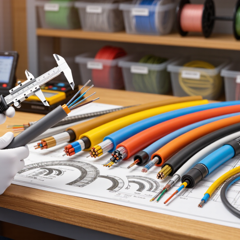
Table of Contents
[Hide]
Classify Duct Cables by Fiber Count, Diameter, and Installation Method
How to Choose the Right Duct Cable for Your Needs?
Classify Duct Cables by Fiber Count, Diameter, and Installation Method
Start with fiber count. A small access route may need 12 or 24 fibers, while a metro backbone often requires 144, 288, or more. The Fiber Broadband Association’s 2024 deployment reports show continued growth in fiber-to-the-premises construction, increasing demand for scalable cable designs. Extra fibers can protect future capacity, but they also increase diameter, weight, and installation tension.
Diameter must match the duct, not just the fiber count. The Telecommunications Industry Association recommends maintaining practical space for cable movement and thermal expansion. A cable that fits tightly may resist air blowing and suffer higher friction. Measure the inner duct diameter, bends, pulling length, and allowable fill ratio. Small differences matter. I would not trust a catalogue size alone.
Installation method changes the selection. Air-blown cables usually need a lightweight jacket and low-friction surface. Direct pulling demands stronger tensile performance and careful sidewall-pressure control. ITU-T G.657 fiber specifications support reduced bend sensitivity, which helps in crowded routes and sharp cabinets. However, bend-insensitive fiber does not excuse poor routing. I have seen projects choose higher fiber counts, then struggle with access chambers and closure space. The technically larger option is not always the better one.
How to Choose the Right Duct Cable for Your Needs? — Classify Duct Cables by Fiber Count, Diameter, and Installation Method
| Fiber Count | Typical Cable Construction | Typical Outer Diameter | Primary Installation Method | Typical Duct Compatibility | Minimum Dynamic Bend Radius | Suitable Applications |
|---|---|---|---|---|---|---|
| 2–12 fibers | Micro loose-tube or compact single-tube cable | Approx. 4–7 mm | Air-blown installation or light pulling through microduct | Microduct with an internal diameter typically around 8–12 mm | Usually 10–15 × cable diameter | Short access links, building entrances, small distribution branches, and low-density FTTH routes |
| 24–48 fibers | Compact loose-tube duct cable | Approx. 7–10 mm | Air-assisted blowing, jetting, or controlled pulling | Small HDPE or similar smooth-wall duct; commonly 12–16 mm internal diameter | Usually 10–15 × cable diameter | Access networks, campus connections, and moderate-capacity feeder segments |
| 72–96 fibers | Multi-tube loose-tube cable | Approx. 9–13 mm | Blowing, jetting, or pulling with approved lubricant and tension control | Medium-size communications duct; commonly 16–22 mm internal diameter | Usually 10–15 × cable diameter | Urban distribution routes, campus backbones, and medium-density access networks |
| 144 fibers | Loose-tube or central-core high-density duct cable | Approx. 12–16 mm | Preferably blown or jetted; pulling is possible where route tension is controlled | Large HDPE duct; commonly 20–28 mm internal diameter | Usually 10–15 × cable diameter | Feeder networks, metropolitan rings, data-center interconnects, and high-growth corridors |
| 288 fibers | High-density loose-tube or ribbon-compatible duct cable | Approx. 15–21 mm | Blowing or jetting is generally preferred; pulling requires careful tension monitoring | Large duct with adequate clearance and low internal friction; commonly 25–35 mm internal diameter | Usually 10–15 × cable diameter | High-count feeder routes, regional aggregation networks, and routes with limited duct space |
| 432–864 fibers | High-density ribbon or mass-fusion-splicing cable | Approx. 18–28 mm | Engineered blowing or jetting installation; route design and duct capacity are critical | Large, smooth-wall duct sized according to the cable diameter and installation equipment | Typically 10–20 × cable diameter | Large backbone routes, central offices, major data-center corridors, and high-capacity metropolitan links |
| 12–48 fibers | Armored loose-tube duct cable | Approx. 9–15 mm | Direct pulling through duct; blowing may be possible for suitable constructions | Standard communications duct with additional clearance for the armor layer | Usually 15–20 × cable diameter | Routes exposed to rodents, construction activity, or higher mechanical risk |
| 48–144 fibers | Water-blocked loose-tube cable | Approx. 10–17 mm | Pulling, jetting, or blowing depending on sheath friction and cable design | Sealed or smooth-wall underground duct with sufficient clearance for water-blocking materials | Usually 10–15 × cable diameter | Underground routes, wet environments, long-haul access sections, and ducts with water-ingress risk |
| 24–96 fibers | Low-friction microduct cable | Approx. 5–12 mm | Air-blown fiber installation using compressed air and a compatible microduct system | Microduct internal diameter commonly about 1.5–2.0 times the cable diameter | Usually 10–15 × cable diameter | Rapid network expansion, congested ducts, urban FTTH deployment, and staged capacity upgrades |
| 96–288 fibers | Dry water-blocked, high-count loose-tube cable | Approx. 12–21 mm | Blowing or jetting for long routes; controlled pulling for short, straight sections | Dedicated duct selected to keep the cable-to-duct ratio within the installer’s specification | Usually 10–15 × cable diameter | Long underground links, network consolidation projects, and high-capacity distribution routes |
Selection note: The dimensions and bend-radius values shown are typical industry ranges rather than universal limits. Always confirm the cable manufacturer’s datasheet, maximum pulling tension, coefficient of friction, minimum installation temperature, duct inner diameter, route length, and the requirements of the selected blowing or pulling equipment before installation.
Related Posts
-
How to Choose the Best Electric Cable Duct for Your Project?
-

10 Best Cable Cover Solutions for a Tidy Home or Office?
-
Top Benefits of Using Cable Cover for Home and Office Safety?
-
What is an Electric Cable Duct and Its Importance for Buyers?
-
2025 Guide: How to Choose the Best Wire Duct for Your Cable Management Needs
-
2026 Best Cable Ducting Solutions for Your Home and Office?